OPERATIONAL
AMPLIFIERS
Operational
amplifiers are linear devices that have every one of the properties required
for almost perfect DC intensification and are in this manner utilized broadly
in signal molding, sifting or to perform scientific operations, for example,
include, subtract, combination and separation.
An
Operational Amplifier, or operation amp for short, is generally a voltage
intensifying device intended to be utilized with outside feedback components,
for example, resistors and capacitors between its yield and info terminals.
These feedback components decide the subsequent capacity or
"operation" of the enhancer and by goodness of the diverse feedback
setups whether resistive, capacitive or both, the speaker can play out a wide
range of operations, offering ascend to its name of "Operational
Amplifier".
 |
| Basic Operational Amplifier |
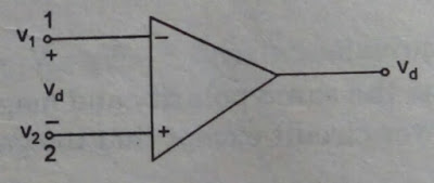
An
Operational Amplifier is fundamentally a three-terminal device which comprises
of two high impedance inputs. One of the information sources is known as the
Inverting Input, set apart with a negative or "short" sign, ( – ).
The other info is known as the Non-rearranging Input, set apart with a positive
or "in addition to" sign ( + ).
A third
terminal speaks to the operational amplifiers yield port which can both sink
and source either a voltage or a current. In a linear operational intensifier,
the yield signal is the enhancement factor, known as the amplifiers gain ( A )
duplicated by the estimation of the info signal and relying upon the idea of
these information and yield signals, there can be four distinct arrangements of
operational amplifier gain.
• Voltage – Voltage "in" and
Voltage "out"
• Current – Current "in" and
Current "out"
• Transconductance – Voltage
"in" and Current "out"
• Transresistance – Current "in"
and Voltage "out"
 |
| Complete representation of OP-AMP |
Differential Amplifier
Differential
Amplifier is a device which is used to amplify the difference between the voltages applied at its
inputs. Such circuits can be of two types viz.,
1. Differential amplifiers built using transistors,
either Bipolar Junction Transistors(BJTs)
or Field Effect Transistors (FETs)
 |
| Differential Amplifier |
Here the input signals (V1 and V2) are applied to the base of the transistors while the output is collected across their collector terminals (Vo1 and Vo2).
In this case, if the V1 at Q1 is sinusoidal, then as V1 goes on increasing, the transistor starts to
conduct and this results in a heavy collector current IC1 increasing the voltage dropacross RC1, causing a
decrease in Vo1. Due to the same effect, even
IE1 increases which increases the common emitter
current, IE resulting in an increase of voltage drop across RE.
This means that the
emitters of both transistors are driven towards positive which inturn implies that
the base of Q2 would start to become more and
more negative. This results in a decrease of collector current, IC2 which inturn decreases the voltage drop across the
collector resistor RC2, resulting in an increase in
the output voltage Vo2. This indicates that the
changes in the sinusoidal signal observed at the input of transistor Q1 is reflected as such across the collector terminal
of Q2 and appear with a phase difference of 180o across the collector terminal of Q1. The differential amplification can be driven by
considering the output in the middle of the collector terminals of the
transistors, Q1 and Q2.
Then again, an Op-Amp
working in differential mode can promptly go about as a differential enhancer
as it results in an output voltage given by
1. Open Loop
gain
Open loop gain is the
gain of the Op Amp without a positive or negative feedback. An ideal OP Amp
ought to have an interminable open loop gain yet commonly it extend somewhere
in the range of 20,000 and 2, 00000.
2. Input impedance
It is the proportion
of the input voltage to input current. It ought to be interminable with no
spillage of current from the supply to the inputs. Be that as it may, there
will be a couple Pico ampere current spillages in most Op Amps.
3. Output impedance
The ideal Op Amp ought
to have zero output impedance with no inward obstruction. So it can supply full
current to the heap associated with the output.
4. Band width
The ideal Op Amp
ought to have a vast recurrence reaction with the goal that it can enhance any
recurrence from DC signals to the most noteworthy AC frequencies. In any case,
most Op Amps have constrained data transfer capacity.
5. Offset
The output of the Op
Amp ought to be zero when the voltage contrast between the inputs is zero. Be
that as it may, in most Op Amps, the output won't be zero when off yet there
will be a moment voltage from it.
OP-AMP Pin Configuration:
In a normal Op Amp
there will be 8 pins. These are
 |
| op-amp 741 pins |
- Pin1 – Offset Null
- Pin2 – Inverting input INV
- Pin3 – Non inverting input Non-INV
- Pin4 – Ground-Negative supply
- Pin5 – Offset Null
- Pin6 – Output
- Pin7 – Positive supply
- Pin8 – Not connected
Gain In Op-amplifier:
·
Voltage gain – Voltage in and voltage out
·
Current gain – Current in and Current out
·
Transconductance – Voltage in and Current out
·
Trans resistance – Current in and voltage out
Application:
Operation Amplifier Applications as
o Inverting Amplifiers
o Non Inverting Amplifiers
o Phase Shifter
o Adder or Summing
Amplifier
o Differential
Amplifier
o Differentiator
o Operation Amp
Applications as Integrator
o Voltage to Current
Converter
o Current to Voltage
Converter
o Logarithmic Amplifier
o Half Wave Rectifier
o Peak Detector
o Voltage Comparator
Read more>> WLAN
Bluetooth Technology


No comments:
Post a Comment